
Introduction
Too often a client will want to jump straight from a preliminary project concept into construction, giving little thought or effort to project planning and engineering. Unfortunately, many of these ill-conceived projects are unsuccessful in their execution due to faulty or non-existent planning. To ensure a successful project, it is best to follow established front-end engineering and design (FEED) project development procedures that will give the client and his financiers confidence that the technical process is sound and the financial outcome has a good chance of being realized.
For a description of the steps that all projects go through from feasibility study, raw resource planning, securing a market, engineering, procurement, construction, commissioning and start-up, refer to the article titled “So You Want to Build a Biomass Plant, A Beginner’s Guide to the Project Development Process”, included elsewhere on this website.
Generally, it is recommended that all projects are set up to go through the following formalized development phases:
- Pre-feasibility phase where a market opportunity is identified and rough costs and possible profits established.
- Feasibility study phase, which considers various alternatives with Class 40 order of magnitude budget(s).
- Definition phase, which includes development of a selected concept and Class 25 budget.
- Detail engineering phase with AFE grade Class 10 budget.
Implementation follows detail engineering, and includes:
- Procurement and contracting.
- Construction.
- Commissioning and start-up.
During each project phase, more detail is added, which should lend clarity, enabling the project viability to be continually assessed. Some companies have formal approval procedures and metrics or `gates’ with milestones that every project must successfully pass through before being approved to proceed with the next project phase. In this manner, project development costs are closely controlled and risk assessment is accurate and up-to-date. Such ‘front-end loaded’ (FEL) projects give the client confidence in the `numbers’ and complete control of the project.
One of the most important phases is the Project Definition phase where the project is clearly `defined’, from both technical / process and cost / benefit perspectives. Discussions are initiated with potential suppliers, customers, financiers, regulating bodies, environmental groups and other stakeholders; a plant location is selected; plant layouts are developed; a Class 25 capital cost estimate (CCE) is developed for the preliminary alternative(s); a final alternative is selected for development; and a plan for project execution is established.
This article focuses on the project definition engineering phase, and is written from a process mechanical perspective. Much of the following information is common to all disciplines, but each discipline has its own requirements.
1 Definition Phase / Concept Development
1.1 Project Objectives
Having a clear understanding of the project objectives is paramount. You can’t design a system without knowing what it is that you are supposed to be designing. This sounds quite basic, but is sometimes not clearly defined. Often the client’s various stakeholders have different perspectives of what the objectives should be, and the importance of each objective.
Consequently, it is very important for the client to have a strong project manager / sponsor who has a clear understanding of the project objectives and can keep both the client project team and the constructor’s project team on track. All communications, instructions and reports must pass through the project manager.
It is uncommon for a client to have all the necessary process expertise or engineering manpower required to do a large project, and will often select a consultant engineering company to either do the engineering for him or to represent him as Owner’s engineer.
It is important for the consultant engineer to set up a project design team with a project manager giving good instructions and guidance.
A clear organization chart should be prepared showing the various positions, incumbents and reporting arrangement.
1.2 Kick-off Meeting
Once a project has been awarded to a consultant engineer, one of the first tasks the engineer does is to visit the proposed plant site to meet with the client stakeholders / project team to discuss and confirm their specific requirements and objectives. Topics covered during the kick-off meeting generally include the following:
- Personnel introductions and roles, including client, consultant, other engineers, and sometimes key suppliers or contractors.
- The client’s description of the project objectives and goals; potential alternatives; and a review of the study work completed to date.
- Description of the project battery limits; i.e. – where the project starts and finishes.
- Confirmation of the client’s expectations regarding the engineer’s responsibilities.
- Description of communication protocols, reporting structure and organization chart(s).
- Review of the proposed schedule with important milestone dates.
- Review of the initial budget upon which the project economic progress will be measured.
- Review of health, safety, and environmental requirements.
- Confidentiality.
The kick-off meeting minutes must be documented and distributed to the project team, as should all important meetings where decisions are made.
1.3 Data Gathering
Often, the opportunity presented by the kick-off meeting at the plant site is utilized to gather as much technical data as is readily available. There might not be a lot of information to gather if it is a `greenfield’ site; however, if it is an existing `brownfield’ site, the amount of technical detail to be gathered can be extensive.
Following is a list and description of the technical information that the engineer will likely require in order to do the definition study.
- A description of the raw material to be handled.
- A description of the target finished product.
- Material flow rates.
- A site plan (if existing).
- General arrangement drawings of existing structures, systems and equipment.
- Flow / Process and Control diagrams of existing systems that the new equipment will be tying into.
- Location and details of existing process tie-in points.
- Site drawing showing structures, underground services, fire protection systems, roads, railways, etc.
- A geotechnical soils report, survey and topographical information, if available.
- Plant Site / Mill Conditions.
- A list of standard components that are to be used on the project (if known).
- Location of the electrical room from which electrical power will be drawn (if existing).
- Type of control system required; hard-wired, PLC, DCS.
Normally the engineer will be unable to obtain all of this information immediately, but he can usually get enough information to get started with his work. And of course, if the project is a greenfield installation, then little of this information will be available unless the client is duplicating a mill he has elsewhere.
It is recommended that the engineer request this information beforehand and do a bit of preparatory work before going to site. This would include preparing preliminary site layout(s) of the proposed installation and roughing out a process flow diagram (PFD), suitable for generating discussion.
1.4 Data Storage and Retrieval
Depending upon the client, existing technical information can be readily obtained, or not. Large companies typically have an engineering department where the information is stored. If the department is really good, the information is up-to-date, catalogued and easily retrieved. In this instance, gathering the required information would be quite easy.
If the information is not well organized or is not stored in a single place, then data retrieval can be more time consuming, and you might need to ask a lot of questions to just find out where it might be stored.
If the company is very large and has a central engineering group, the information may not even reside at the local project site.
In some instances, the information won’t exist and the engineer will need to `start from scratch’ and do an extensive field inspection and survey. Normally, a site survey is not done until the detail engineering phase.
1.5 Design Basis Memorandum / Design Criteria
The design basis memorandum (DBM) should be one of the first documents prepared by the engineer during the definition phase, as it sets down the basic design parameters for the project going forward and includes:
- A description of the project.
- Project objectives.
- Type of project – metric or imperial.
- Design criteria including:
- Material information – A description of the material being handled, including material characteristics such as species and mix, material form and mix, basic density, bulk factor, bulk density, moisture content (MC), particle size distribution (PSD), contaminants, temperature, abrasiveness, corrosiveness, flow characteristics, angle of repose, angle of drain, etc.; also, proximate and ultimate data (if required and available).
- Required throughput and process flows.
- Basic design data and a general scope of work for all disciplines is required:
- Civil / structural / architectural.
- Mechanical / piping / HVAC.
- Electrical / controls.
- Transportation
The DBM tends to be a `living’ document with changes occurring throughout the engineering process as new information becomes available and the design is refined.
1.6 Plant Site Conditions / Standard Components
Plant site conditions include information such as:
- Plant location, elevation, seismic data, precipitation, ambient temperatures, wind data, motor power, control power, compressed air requirements, water specifications, etc.
- Standard components that are to be used throughout the plant are often included in the plant conditions document, and include such items as: motors, gearboxes, bearings, belting, idlers, sprockets, RC chain, control devices, hydraulic components, MCC’s, switches, level devices, PLC’s, HMI’s, etc.
Plant conditions are sometimes a stand-alone document, particularly if the plant is existing and already has such a document established.
1.7 Flow / Process and Control Diagrams / Single-Line Diagram
Process Flow Diagrams (PFD’s) are also one of the first documents produced. They are a graphical representation of the main processes showing the equipment used, flow rates, etc., based on preliminary process calculations.
PFD’s are later converted into Process and Control Diagrams (P&C’s) or Process and Instrumentation Diagrams (P&ID’s), which show more detail such as equipment names and numbers, field devices, control symbology and numbers, motor hp, etc.
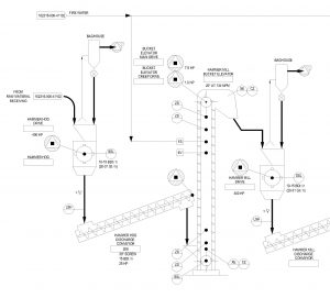
Figure 1 – Clipping from Typical Material Handling Flow / Process & Control Diagram
Single-Line Diagrams (SLD’s) are also developed early in the project process. SLD’s show the basic power sourcing and distribution, motor loads, etc. SLD’s are generally sufficient for definition phase electrical engineering.
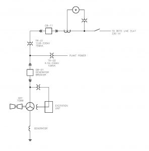
Figure 2 – Simple Typical Electrical Single Line Diagram for Turbine-Generator
1.8 Concept Development
Often different alternatives for achieving the project’s objectives are identified during the feasibility phase and need to be assessed during the definition phase, in order to select the most appropriate arrangement. Some of the alternatives require different process equipment and different equipment layouts, each with its own technical and economic requirements and benefits. It is often necessary during the definition phase to investigate more than one alternative to ensure the best alternative is selected for further development and detail design.
One of the first steps in assessing alternatives is to take the available technical information and prepare a background drawing of the project area upon which each of the various alternatives can be overlaid to determine fit and function.
The alternatives are developed at a very high level, sufficient for discussions with the client, with the intent being that one alternative will be selected for further development.
The engineer then develops preliminary general arrangement drawings (GA‘s) and elevations of the selected alternative. These preliminary drawings are presented to the client for his review to ensure that the consultant is on `the right track’; that what is being proposed reflects the client’s requirements.
The engineer then revises the drawings according to the client’s comments and resubmits the drawings for approval of concept.
Note: The client may already have a pre-existing drawing naming and numbering system to which the engineer should conform.
As mentioned above, design criteria, process calculations and preliminary Flow / Process and Control diagrams are concurrently developed during the definition phase.
The consultant may also develop energy and mass balances for the process during the definition phase.
See the following graphics for examples.
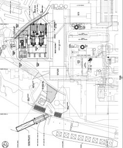
Figure 3 – Typical Clipping from a GA Site Plan
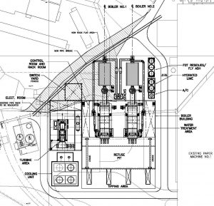
Figure 4 – Typical General Arrangement Plan
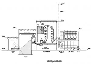
Figure 5 – Typical General Arrangement Elevation
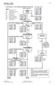
Figure 6 – Typical Mass Balance for a Chip Thickness Screening System
1.9 Equipment Technical Specifications
Preliminary vendor information is usually required for concept development and capital cost estimating, so equipment technical specifications and sketches must be prepared for inclusion in requests for [budget] quotations (RFQ’s).
For a definition study, the technical specifications should be as brief as possible, but as a minimum, should contain the following:
- A brief description of the project and how the specific equipment fits into the project, and a description of what the specific piece of equipment is to do.
- Limits of supply, including a list of the required Vendor Supply components and a list of the excluded components.
- Design criteria including a description of the material being handled / processed, with the target material characteristics and required flow rates.
- Performance requirements.
- Plant operating conditions and required standard components.
- Equipment specifications / requirements for: mechanical, piping, structural, electrical and controls.
- A list of the governing codes and standards that need to be met.
1.10 Requests for Quotations
Requests for quotations (RFQ’s) can be brief for definition studies, but should address the following:
Instructions to Bidders
- A clear statement of the RFQ requirements; i.e. – budget pricing +/-25%.
- Response request; tender submission requirements and RFQ closing time.
- Equipment delivery timing and location.
- Pricing requirements; i.e. – validity, FOB, DDP, etc.
- Warranty and performance guarantee requirements.
- A list of information to be provided with the vendor’s bid package.
Technical Documents
The RFQ should contain relevant technical documents, including:
- Technical specification and associated drawings.
- Geotechnical information.
- Plant / Mill Conditions.
Note: Be careful to observe all non-disclosure agreements (NDA’s) when submitting RFQ’s.
1.11 Master Equipment Schedule / Work Breakdown Structure
A preliminary master equipment schedule (MES) spreadsheet is usually developed during the definition phase, and includes a listing of all the equipment with such information as:
- Equipment name and number – The client may have a pre-existing naming and numbering system.
- Equipment description with capacity, etc.
- Motor size and speed, and load factor.
- Electricity voltage, phase and cycle.
- Sometimes control devices are included in the MES.
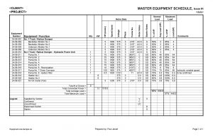
Figure 7 – Sample Master Equipment Schedule
Later in the detail design phase of the project, a work breakdown structure (WBS) is developed that becomes the governing document against which all project charges are recorded.
1.12 Project Schedule
A preliminary project schedule is developed during the definition phase. The schedule must consider:
- The plant’s target start-up date – This is usually the best place to start when developing a preliminary project schedule. Then work backwards through the necessary implementation steps to arrive at a project start date and to determine the available time for tasks.
- Commissioning period.
- Construction period including all discipline work.
- Equipment manufacturing and delivery times.
- Procurement and contracting activities.
- Detail engineering for all disciplines.
- Definition engineering.
- Pertinent required client milestones regarding approvals, permitting, financing, etc.
- Project start date.
Conflicts will occur that could make either the project start date or the plant start-up date unrealistic; however, many of the above activities can overlap to shorten the overall project delivery time.
Refer to the following sample schedule.
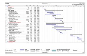
Figure 8 – Typical Simple Project Schedule
1.13 Capital Cost Estimating
The outcome of a definition study is usually a Class 25 (-15%,+25%) budget capital cost estimate (CCE) that the client can utilize in his financial modelling.
A capital cost estimate should include direct costs, indirect costs and contingency; and may or may not provide for escalation.
Direct Costs
Direct costs are `hard’ project costs for each item, which include the following for each discipline:
- Direct purchase price of goods or service.
- Installation contractor purchases, including concrete, steel, tool rentals, sub-contractors.
- Contractor installation labour.
Indirect Costs
Indirect costs are `soft’ project costs that are not included in direct costs and could include allowances for such things as:
- Engineering.
- Owner’s project development costs.
- Construction management.
- Construction living out allowance (LOA) and travel.
- Temporary construction facilities.
- Construction insurance.
- Vendor equipment erection supervision.
- Commissioning and start-up assistance and training.
- Premium labour costs (overtime).
- Spare parts.
- Taxes and Duties.
The amount included for indirect costs depends upon the client’s company policies, and the items included can vary substantially, depending upon the client. An average allowance to use is 25% of the total direct costs.
Contingency
A contingency allowance should be provided in the CCE to cover those costs that are unforeseen at the time the estimate is produced and may become apparent as detailed design and construction proceed. The contingency is not intended to provide for costs associated with scope changes.
The amount of contingency to allow depends upon the client’s company policy, which should consider the amount of engineering and procurement work undertaken to produce the CCE and can vary between 5% and 25% of total direct and indirect costs. The greater the project definition, the lower the contingency required.
Amount of Engineering Required
You don’t want to do any more engineering than is required to satisfy the requirements of the current project development phase. For example, you would not want to expend the effort to do complete detail design until you knew the project was technically and financially viable and you had MOU’s in place with most of the stakeholders (resource suppliers, market clients, lenders, etc.).
Depending upon the project complexity, a minimum of 5-10% of the total project engineering should be completed for a definition study. Some clients require an AFE grade Class 10 estimate at the end of the definition phase, and the amount of engineering and procurement is significantly greater at 25-35%.
Budget Pricing
Preliminary vendor budget pricing is required to develop a Class 25 budget capital cost estimate. Short technical specifications need to be developed and +/-25% budget pricing requested. When evaluating bids, it is recommended that you resist the urge to use the lowest priced quotation in your capital cost estimate, as that leaves you no room to maneuver when you get to the procurement stage.
Material Take-Offs
Where vendor pricing is not available, material take-offs (MTO’s) are required to estimate the amounts of all required components including: civil works, structural foundations and steelwork, mechanical equipment, steelwork and HVAC, piping, electrical and controls.
Contracting Estimating
In addition to the hard equipment and material costs, the estimator must consider installation labour, contractor purchases, mobilization and demobilization, equipment rentals, straight-time and overtime labour rates. If the estimator doesn’t have up-to-date information regarding the appropriate rates at the project location or the type of construction required, he may initiate preliminary discussions with potential contractors regarding unit pricing.
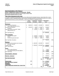
Figure 9 – Sample Order of Magnitude Capital Cost Estimate
1.14 Project Execution Plan
A project execution plan should be developed during the definition phase for the project going forward defining:
- The type of project, i.e. – conventional; engineer, procure and construct (EPC) or design-build; or engineering, procurement and construction management (EPCM).
- A list of the required `actors’ in the project and their roles and responsibilities. i.e. – client, engineers, vendors, contractors.
- The steps necessary to efficiently implement the project.
- The project schedule.
- The engineering requirements.
- The procurement and contracting tasks.
1.15 Study Report
Typically, all of the above information is combined in a Project Definition Report, which is usually written by the consultant engineer with input from the client. The report is first issued to the client for review and comments and then revised to suit and reissued for the client’s files.
By the time that the definition study is complete and the report issued, the project should be well defined with few unknowns left to resolve. The client should have high confidence in the viability (or not) of the project and that the project is ready to proceed into the detail engineering phase.
2 Detail Engineering Phase
Detail engineering follows the definition phase. During detail engineering, all necessary details required to construct the project are worked out. The detail engineers use the definition study as their starting point and guide through the rest of the process.
Detail engineering includes:
- Preparing a detailed project schedule.
- Confirming process design and calculations.
- Preparing general arrangement drawings.
- Preparing detail drawings sufficient for firm-price procurement and contracting purposes (all disciplines).
- Preparing technical specifications for equipment purchases.
- Reviewing vendor information.
- Preparing detail design drawings based on the selected vendor’s equipment.
- Preparing scopes of work for civil / structural contracts, mechanical / piping contracts, and electrical / instrumentation contracts.
- Writing a process functional specification (process narrative) and a control narrative defining the process control requirements.
Often more precise information is required during detail engineering, including:
- Detailed surveys of specific locations.
- Geotechnical work including taking soil samples.
- Taking field measurements of existing equipment.
- Inspections of existing electrical and control systems.
Regular drawing issues should be made to keep everyone informed and two design review meetings would be held at the 25% and 50% design completion points; the purpose being to give the client the opportunity to make changes before the detail design progresses too far.
Site Survey
A site survey is required for detail engineering; however, much of the survey information may already exist somewhere in the client’s files.
If you decide to do a survey, then get a dimensioned site plan drawing from the client and check the presence and locations of existing structures and equipment against the drawing.
Other Activities
The following items are normally done during the detail engineering phase:
- Procurement activities including issuing price inquiries, preparing bid evaluations, negotiating and awarding purchases, expediting deliveries (These can be done by the client, the engineer or the contractor).
- Contracting activities including preparing contract documents, issuing the contracts for tender, preparing comparisons of tender, negotiating and awarding contracts (usually done by the client or engineer).
- Often permits are required; these are normally prepared and submitted by the client, but he usually needs project specific information provided by the engineer, in order to do so.
- Establishing an accounting grade, Class 10 CCE.
3 Construction Phase
Construction often starts before detail design is complete. The civil / structural work is started first, followed closely by mechanical / piping; electrical / instrumentation would follow some time later.
Sometimes the client manages the construction; sometimes he hires a third party to do so.
Construction not only includes the actual erection and installation, it also includes:
- Health, safety and environmental considerations.
- Scheduling.
- Procuring materials.
- Sub-contracting.
- Project accounting.
- Quality control.
4 Commissioning and Start-Up Phase
Commissioning and start-up follow construction and include:
- Rotation checks.
- Control and logic checks.
- Safety device checks.
- Dry running the equipment; then short runs with material.
- Making flow adjustments.
- Operational training (by client).
- Developing safe work procedures (client).
- Actual start-up and running at production levels.
- System performance checks.
GLOSSARY
AFE application for expenditure
CCE capital cost estimate
DBM design basis memorandum
DCS distributed control system
DDP delivery, duty paid
EPC engineer, procure and construct
EPCM engineer, procure and construction management
FEED front-end engineering and design
FEL front-end loading
FOB free on board
GA’s general arrangement [drawings]
HMI human machine interface
HVAC heating, ventilation and air conditioning
LOA living-out allowance
MC moisture content
MCC motor control centre
MES master equipment schedule
MOU memorandum of understanding
MSW municipal solid waste
MTO material take-off
NDA non-disclosure agreement
PLC programmable logic controller
PFD process flow diagram
P&C process & control diagram
P&ID process & instrumentation diagram
PSD particle size distribution
RC roller chain
RFQ request for quotation
SLD single line diagram
WBS work breakdown schedule
Other Articles
Other articles related to project implementation can be found on this website, including:
- “So You Want to Build a Biomass Plant”
- “Vendor Documentation Requirements”
- “A Practical Guide to Metrication”
Copywrite © 2016
About the Author
Paul Janzé has more than 30 years of experience in engineering design, project management, equipment manufacturing and maintenance, primarily in the forest products and energy industries. His industrial material handling experience includes: biomass handling and processing including forest residuals, logs, lumber, chips, pellets, woodwaste, corn stover, straw and poultry litter, deinked pulp, sludge and biosolids; and other non-biomass materials including municipal solid waste (MSW), limestone, coal, ash and petroleum coke.
He has a keen interest in technologies which recover and utilize waste materials and convert them into useful products. Paul’s specialties are fibre flow analysis and mass balances, process optimization and designing novel solutions to complex processing and handling problems.
Paul can be reached at: Advanced Biomass Consulting Inc., tel: 604-505-5857, email: pjanze@telus.net .
Hi!
You have such a grate expertise in biomass production engineering.
Would you share some knowledge ,if you have on hemp cellulose biomass production?
My intention is to start a hemp based biomass production.
I am a Product Designer. Fall in love with Zeoform, Australian based company,that makes products out of hemp based biomass.
Sincerely, Vivita.
Hello Vivita,
Thank you for visiting my website, and I am glad that you enjoyed the articles.
Like most biomass materials, handling and processing hemp has its specific challenges. Let me know what challenges you are having and I may be able to provide assistance.
Paul Janze
Advanced Biomass Consulting Inc.