
Author: Paul Janzé, Advanced Biomass Consulting Inc.
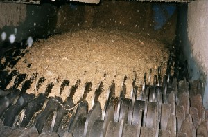 The disc screen is a simple piece of equipment that is ideal for, and commonly used for screening woody biomass. It consists of a series of driven shaft assemblies mounted in a frame. Each rotor shaft assembly has profiled discs mounted at regular spacings. The discs from one shaft interleaf with those on the adjacent shafts, creating open areas between the discs and the shafts.
Incoming material is fed onto one end of the screen. The shaft assemblies rotate, and the discs agitate the material. Pieces of material that are smaller than the spacing between the discs and shaft assemblies fall through the screen. The pieces that are larger than the openings are conveyed along the top of the discs and pass over the end of the screen.
Disc screens are particularly useful for screening biomass for the following reasons:
- They provide good agitation, which is necessary for separating the biomass particles which tend to knit together.
- They are designed to handle rocks and other large, heavy contaminants without damage.
- They will withstand a lot of wear from abrasion.
Disc Screens can be used for:
- Scalping screens, where the object is to remove oversized material from the product flow. The oversized reject material passes over the end of the screen and the acceptable sized material passes through the screen.
- Unloading screens, where the object is to remove undersized material from the product flow before a downstream process; the undersized reject material passes through the screen and the acceptable sized material passes over the end of the screen.
- Thickness screens, where a precise material thickness is required.
There are many disc screen manufacturers and many styles of screens. The purpose of this article is to provide some general design fundamentals. The paper focuses on the scalping screen application, but many of the comments are applicable to all disc screens. Disc screen design is more of an art based on experience than on science.
Disc Screen Sizing
Disc screen size is determined by:
- The volume of incoming material. The screen must accommodate both average flow and surges.
- Particle size distribution (PSD); that is, how much material is smaller or larger than the required product size and the percentage of each.
- Required product size; e.g. – the required size is specified as 90 -95% <4” (or <100mm), meaning all material passing through a sample test screen with a 4” (100 mm) round hole screen plate.
Disc Screen Capacity
Disc screen capacity depends upon the amount (%) of screen open area, which is defined by establishing:
- The number of rotor shaft assemblies
- The disc Interface Opening (IFO)
- The screen Slot Length
- The disc thickness
- The spacer collar diameter
- Screen width and length
- Rotor speed
The amount of screen open area has an effect on the total screen footprint; the smaller the percentage of open area, the larger the screen footprint must be for any given screen throughput.
Quantity of Rotor Shaft Assemblies
The number of shaft assemblies defines the length of the screen and depends upon the length of time required for all undersized material to percolate down through the material bed and pass through the screen. The determining factors are:
- Width of the screen
- How well the material is spread across the width of the screen
- The cohesiveness of the material being handled
- The amount of undersized material in the flow
- The maximum possible surge flow
Disc screens should be sized such that under the maximum possible flow conditions, all the undersized material has passed through the screen with at least 1-2 rotors clear at the end of the screen.
Slot Length and Disc IFO
Disc screen openings have two dimensions (slot length and IFO). Theoretically, the maximum sized piece that can pass through a scalping screen is one that has the dimensions of the IFO and slot length and is of an infinite length. Practically speaking, if screens are fed properly such that long pieces are not allowed to fall end-wise onto and through the screen, the maximum piece passing through a screen will be a little bit longer than twice the slot length. Hence it is desirable to keep the slot length as short as possible in order to reduce the size of the longest piece passing through the screen.
Slot length is the distance between adjacent shaft assembly spacer collars and is determined by:
- Rotor spacing
- Spacer collar diameter
- Disc diameter and clearance between tip of one disc and collar of adjacent shaft
The disc Interface Opening (IFO) is defined as the spacing between interleafed discs on adjacent shaft assemblies. Generally, it has been learned from experience that the disc interface opening (IFO) should be somewhat smaller than the target product size; e.g. – IFO = <3″ for a target size of <4″.
Screens may have one or more disc IFO’s. It is advisable that the first 2 – 3 rotors to be sliver orientation rotors, which have a narrow IFO of < ¾”, the idea being to encourage long pieces of wood to lie down on the screen and to prevent them from diving through the screen.
In some screening applications, multiple size classifications may be required where fine material is removed in the first part of the screen and larger fractions in the middle and last screen sections.
Disc IFO and screen width dictates the number of discs required on each shaft assembly.
IFO is fairly easy to change, so when selecting a screen, the most attention is paid to getting the correct IFO in order to get the correct product sizing. As noted above, slot-length is determined by the basic machine design. However, paying attention to the slot-length is important, too, when selecting a screen. Slot-length is particularly important when selecting screens that are screening small material.
Rotor Spacings
The minimum rotor spacing is usually limited by the space required to accommodate shaft assembly bearings or the inter-rotor drive components. The rotor spacing must match the actual inter-rotor drive roller chain or cogged belt sprocket center distance precisely in order to maintain a tight drive. Roller chain drives should have oil lubrication to reduce wear.
Rotor Discs
The rotor discs are mounted at pre-determined spacings on the disc shaft. The discs can be clamped between spacers or permanently fixed to the shaft by welding. The lowest cost screens use welded discs, but when the discs have worn out the entire shaft assembly must be discarded and replaced. Also, care must be taken so as to not weaken the shaft when welding the discs to the shaft.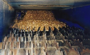
A better rotor design utilizes discs with square holes, which are slid onto square shafts and separated by round spacer collars. A threaded locking mechanism is utilized to tighten the discs firmly on the shaft. It is necessary that the appropriate thread (left hand or right hand) is used to prevent the locking nut from loosening during rotation.
The advantages of this design include:
- Discs can be replaced when worn out.
- The possibility of disc-to-shaft weld failure is eliminated.
- The discs are positively driven by the square shaft.
- If desired, the disc spacing can be changed by replacing the spacer collars separating the discs.
The periphery of the discs is profiled to provide agitation. The shape of the profile depends upon the material being handled and the vendor’s specific design. Generally, 6-point stars are used for wood chips and discs with 6 rounded lobes are used for hog fuel and other stringy biomass.
Disc Metallurgy and Thickness
Scalping screens require discs made of an abrasion resistant steel with a Bhn >360.
Biomass scalping screen discs are generally 3/8” thick. However, most of the fines containing sand, dirt and grit fall through the first few rotors and this part of the screen is subject to the highest wear. Therefore it is advisable to utilize somewhat thicker discs (1/2”) in this part of the screen.
Disc Outside Diameter
The tips of the disc points or lobes should have minimal clearance (~1/4”) to the adjacent shaft assembly collar; this dictates the maximum disc outside diameter.
Screens with a large disc diameter and small collar diameter provide greater agitation and a greater % open area, so can have an overall smaller footprint. However, they have a longer slot length and will tend to pass longer pieces of material.
Rotor Speed
Experience has determined a nominal rotor speed of approximately 30-50 rpm for most woody biomass depending upon disc and spacer collar outside diameters. Some applications may call for a gradually increasing speed between shafts to further separate and pull apart the interlocked material on the screen.
Generally, increasing overall screen speed will increase the amount of material rejected over the end of the screen and have the effect of increasing screen capacity. Conversely, decreasing the speed increases the dwell time and increases the amount of material passing through the screen but decreases screen capacity. Note: the effect is not linear.
Screen Width
As a minimum, disc screens should be somewhat wider than the feed conveyor; for example, a 48” or 54” wide screen for a 42” belt conveyor. However, the most important factor for determining screen width is the amount of material being delivered to the screen. For a given volume of material, a narrow screen will have a much deeper bed depth of material than will a wide screen and it will take much longer for the undersized material to percolate down through the bed.
Conversely, it can be difficult to spread the incoming material across the width of a very wide screen. This can sometimes be done with deflector plates but on very wide screens a distribution screw or similar device might be required, depending upon the material being screened.
Shaft Assembly Bearings
Some disc screen designs utilize flanged bearings which are OK from a load perspective; however care must be taken to mount them outboard of the screen frame where material cannot get jammed into the bearing seals. Flanged bearings are useful where you need the shaft assemblies to be closely spaced.
Bearings are subject to high side loads due to material wedging between adjacent rotating discs. Therefore, one bearing on each shaft, usually the one on the drive side, should be firmly anchored against a shoulder on the shaft, in order to prevent the shafts from shifting sideways in the bearing.
Shafts secured only with adapter-mounted bearings are not secure enough to prevent rotor shafts shifting laterally, thereby disrupting the IFO accuracy.
The best screen design utilizes pillow block bearings mounted outboard of the screen frame. The PB bearings are located with bearing keepers welded to the frame. This arrangement has the following advantages:
- It eliminates the problem of slivers jamming through and ruining the bearing seals
- It provides for a stronger frame
- It enables the shaft assemblies to be easily lifted off of the screen
For bearing interchangeability, it may be necessary to machine the ends of each bearing base to produce a uniform pillow block length.
Dust Seals
The shaft assemblies should be equipped with UHMW plastic dust seals located on the outside of the frame, the intent being to minimize fugitive dusting around the shaft where it passes through the frame.
Drives
It is common to drive one rotor shaft directly from a gearbox and then drive the other shafts from the first shaft with inter-rotor drive chains or belts. Due to the shock loads that can develop in a disc screen it is best to limit the number of shafts driven from any one drive to 8 or less. For example, on a 12-rotor screen you would used two drives instead of one, with each one driving 6 rotors.
Gearboxes can be shaft-mounted or foot-mounted and direct coupled to the screen or have a low-speed chain drive. Motors can be C-flange mounted or direct coupled to the gearbox or have a V-belt high speed drive.
Inter-rotor Drives
Each rotor must be driven. The usual method is to drive one roll from the next with a roller chain drive located on one side of the machine. For this application, double-single sprockets keyed to the shaft are required. Alternatively, single sprockets can be located on each end of the rotor shaft.
Serpentine roller chain drives have also been utilized, where a single chain passes over each successive sprocket. However, this application is limited to light duty screens due to the low number of sprocket teeth engaged in the chain. The roller chain wrap can be increased by utilizing idler sprockets between each rotor, but this requires a lot of space and is more complex than separate roll-to-roll drives.
Roller chain drives require lubrication to reduce wear and prolong life. Properly designed oil bath chain guards that minimize the ingress of dust are the best.
Cogged belt drives have also been for inter-rotor drives. However, they require considerably more space than roller chain. They have the advantages of being much quieter and not requiring lubrication.
It is usual to put the inter-rotor drives on one side of the machine and the main drive(s) on the other side.
Disc screens should have slow speed switches on the last roll in any drive sequence. The slow speed switch can be utilized to detect a broken drive chain or a drive which has stalled due to a jammed screen.
Anti-Jam System
Disc screens can be jammed by wedge-shaped rocks, metal, large pieces of wood, wire or stringy bark. Consequently, it is advisable to have an anti-jam system on every disc screen.
When a screen section jams, it is detected by the slow speed switch, which sends a signal to the PLC. The PLC then initiates the following run sequence:
- Start-up and run in reverse for 2 – 3 seconds, then stop.
- Start-up and run forward.
- If still jammed, run the reverse / forward sequence for a maximum of 3-4 times and if still jammed, then shut the screen down and signal the operator to attend to the machine.
The screen drives should be interlocked to preceding conveyors such that they will stop when the screen stops.
Feed Onto Biomass Disc Screens
Generally when handling biomass, it is best to have the screen in-line with the feed conveyor, particularly where you have long pieces and big chunks of wood. Try to avoid turns of 90° onto the screen, but if necessary, provide for extra height and a long, wide chute to allow the big pieces to turn. Pre-hogged material coming direct from upstream hogs should not contain many big pieces, so feeding at 90° should be OK.
The material should not drop directly on the top of the screen discs, as long thin pieces will dive straight through the screen.
The infeed chutework should be designed so as to evenly spread the material across the width of the screen. Diverters or deflectors can be added to the chutework if necessary, as long as they don’t impede the flow onto the screen.
The infeed chute before the screen should be at least 55° from the horizontal.
The screen should have a short integral infeed chute and impact plate above the first rotor to bridge the gap between the screen end plate and the first rotor. The impact plate is profiled with fingers that fit closely to the discs and collars of the first rotor and is sloped at approximately 35° from the horizontal, the intent being to deflect long slivers horizontally onto the screen.
Chutework
Acceptable material passing through the screen will contain the smallest particle fraction, which will fall through the first part of the screen. This fraction also contains most of the sand, dirt, grit, snow, ice, etc., which can build-up on the chute plates underneath the screen in areas which are not scoured clean by the falling larger particles. Build-up can be particularly bad in the valley angles between intersecting chute plates. The chute plates should be as steep as possible, with valley angles at a minimum of 55° from the horizontal. Dribble chutes outside of the main flow should be >60° from the horizontal. Sliding surfaces should be constructed of steel plate at least ¼” thick. In particularly high wear areas a wear liner could be considered. UHMW liners can be used to minimize material sticking or freezing to the chutework.
Reject material passing over the end of the disc screen can be quite big. The reject chutework should be designed sufficiently strong to handle the impact of large pieces of wood. Ideally as with feed chutes, material which contains gross oversized pieces that are rejected over the end of the screen, should not be made to turn through 90° chutes. However, this is not always possible to avoid; therefore, the chutes should be wide enough to pass the largest piece rejected.
Large inspection / access / cleanout doors should be provided in all chutes. Plugged chute switches should be located in chutes wherever there is the possibility that chutes will plug up with material.
Screen Elevation
The elevation of the screen is determined by the elevation of the equipment or bunker into which the screen is discharging. The screen must be high enough above the downstream equipment or bunker to discharge with suitable chute angles.
Most disc screens are mounted on the horizontal, but in some applications work best with either a slight incline or decline.
Screen Maintenance
Properly designed and constructed disc screens are rugged pieces of equipment that typically run for long periods of time without shutting down for maintenance; so much so, that preventative maintenance is often overlooked until the equipment is in poor repair. Screens typically run all year without major servicing.
The screen should be located in the system such that it can be bypassed or physically removed from the process with minimal effort. This can achieved by mounting the screen on wheels and rails so that it can be pulled sideways or lengthways out of operating position. Typically, temporary chutework is put in place so that the system can still run when the screen is out of position. Alternatively, a flop-gate can be installed on the feed chute to the screen, which will bypass the material around the screen. When the screen has been bypassed or removed, care must be taken not to jam up downstream equipment with gross oversized pieces of wood.
Dust Control
Processing dry wood and bark through disc screens can be very dusty, so the screen should be equipped with sealed covers. All components of a system including conveyors, chutes and screens should be properly enclosed and ventilated in order to keep a negative pressure inside the equipment, thereby minimizing fugitive dusting.
Reprocessing Screen Rejects
Gross oversized screen rejects can be:
- Discarded in a landfill if heavily contaminated with rocks
- Reprocessed though a secondary hog and reintroduced into the processed hog fuel flow.
Other Varieties of Disc Screens
Star screens utilize interlocking flexible finger-discs on high speed shafts and are suitable for light, sticky materials such as straw, poultry litter or compost. These are not suitable for handling large, heavy chunks of wood. They have a large open area but are not very precise.
Delta screens utilize delta shaped in-line discs forming a consistent sized opening between the discs and shafts. They are quite precise but tend to have a low open area requiring a large screen footprint.
Updated December 2020
Copyright © December 2020
About the Author
Paul Janzé has more than 30 years of experience in engineering design, project management, equipment manufacturing, plant trouble-shooting, optimization and maintenance, primarily in the forest products and energy industries. His biomass handling and processing experience includes forest residuals, logs, lumber, chips, bark, woodwaste, wood pellets, wood strands, straw and poultry litter, animal tissue, sludge and biosolids. Additionally, he has experience with other industrial materials such as municipal solid waste (MSW), limestone, lime dust, coal, boiler ash, sand and petroleum coke.
He has a keen interest in technologies which recover and utilize waste materials and convert them into useful products. Paul’s specialties are fibre flow analysis and mass balances, conceptual design, process optimization and designing novel solutions to complex processing and handling problems.
Paul can be contacted at: Advanced Biomass Consulting Inc., tel: 1-604-505-5857, or by email at: pjanze@telus.net
can you explain a little more about the disc screen chains and their role in having a smooth running disc screen?
Hi Cody,
Thanks for visiting my website. I’m glad that you found the article on disc screens helpful.
If the inter-roll chains do not fit properly (nice and snug), you will get excessive wear and slackness. The nature of the rotating screening action causes the tight-side, slack-side tension to vary with the end result of loose chains being rotors and chains that jump and snap. It is very important when designing a disc screen and selecting roller chain drives that the shaft center distances exactly match the roller chain pitch and that the chains be adequately sized and lubricated to ensure long life.
I have designed many disc screens and provided trouble-shooting for many more.
Are you having a roller chain problem with your machine? If so, I might be able to help you trouble-shoot your screen and provide recommendations.
Let me know if you are interested.
Paul
Fist off thank you for your response. Yes we were having a problem with sizing the chains correctly. We have 100 size chain on our screen and with slack in chain just as you said the machine will start popin and jumping links. Our problem was if we took a link out the chain was to short and the length it was the chain was too loose. I decided to carve a piece of UHMW to the slack of the chains and stopped the jumping and popin and the machine ran a lot smoother
Cody,
Good solution. I am assuming that you put the UHMW tighteners on the slack side of the chain, which will be OK as long as you don’t try to run the screen a prolonged time in reverse. Keep an eye on the UHMW and replace them before they wear too badly.
Paul
The following email string is between the website author and a Phd student that I have chosen not to identify. I thought the discussion may be of interest to others.
Admin
Quote:
From:
Sent: Sunday, January 3, 2016 3:24 AM
To: pjanze@telus.net
Subject: open area of a disc screen
Hi Paul,
Hopefully after a long time surfing I could find some interesting infos about disc screens. Thx for sharing that in your website! my phd thesis (still in progress) is about cardboard disc screen and its application in waste paper sorting. The disc screen that I work with is functunally similar to what you wrote about it but its triangular discs are made from rubber. The most difficult part of my thesis is finding a calculation procedure for disc screen open area! Do you have any idea / solution for that? If you need more details about it, please let me know.
I appreciate for your response.
Regards,
A__
On Mon, Jan 4, 2016 at 1:35 AM, Paul Janze wrote:
Hi A__,
Thanks for visiting my website.
I like to know a bit about the person I am communicating with. So, please tell me about yourself, your university, where you are from, your project, etc.
I have worked with `delta’-shaped disc screens, which are somewhat triangular and with flexible `star’ screens.
I should be able to give you some guidance if I know a bit more about your project.
Paul Janze
Advanced Biomass Consulting Inc., Langley, BC Canada
pjanze@telus.net
From:
Sent: Monday, January 4, 2016 1:21 AM
To: Paul Janze
Subject: Re: open area of a disc screen
Hi Paul,
Thanks for your respond! I am doing my phd since 2011 in department of processing and recycling in _________ university.
My thesis topic is ” ________________” but one of the main questions in this research is finding a method for calculating the open area of disc screen (see enclosed pix of disc screen).
Unfortunately there are very very limited infos about open area calculation of disc screens in internet. Regarding to your experience about disc screens, I hope that you can help me on this issue.
If the attached pictures are not clear or if you need more infos, please let me know.
Regards,
A__
Hi A__,
Open Area of a Disc Screen
1. A simple description is: when looking straight down on a disc screen the % open area is the visible open area through which particles can fall divided by the total inside area of the screen.
2. The dimensions of the main open area are the distance between the interlocking discs, called the interface opening (IFO) times the distance between the rotor shafts, called the slot length (SL). The total area is the resulting area times the number of openings.
3. Additionally, you need to account for the area between the tip of the disc and the adjacent rotor shaft. Keep in mind that each disc has peaks and valleys, so the distance between the disc tip and the adjacent shaft is the average of the two. The area then is the aforementioned average multiplied by the thickness of the disc. The total area is the tip area times the number of discs.
4. Because of the agitating nature of disc screens, I’m not sure how useful knowing the open area is, other than as a rough guide for sizing the screen or for comparing the overall footprint efficiency.
5. A disc screen’s capacity and efficiency depend upon much more than its total open area, including:
– The material being handled.
– The IFO and SL.
– The size and shape of the discs.
– The material that the discs are made of.
– The speed of the rotors.
– The screen inclination or declination.
Delta-shaped Discs
1. I note in your photos that the shape of the `triangular’ discs are a rounded delta-shape, very similar to those used by `Bulk Handling Systems’ on their `Debris Roll Screen’, which they use for biomass screening and refuse screening including waste paper. See their website at:
http://www.bulkhandlingsystems.com/comparisons/debris-roll-screen-vs-trommel-screen/
2. The big difference between your screen and the BHS roll screen is that your discs are not in-line as they are on the BHS screen. The advantage of the BHS screen is that the opening between the discs and shafts remains constant due to the delta shape of the discs.
I hope this answers your query OK. If you have any other questions or comments, please contact me.
Paul
Hi Paul
Thanks for a very interesting & informative article.
I hope i`m not disturbing you over 5 years after the publication of this paper, i am currently in the process of attempting to design a disc screen in order to screen woodchip for biomass boilers. The European classification for the chip i require is ONORM M7 133, G30 which specifies that the majority of the chip is 16mm.
The chip is chipped with a flywheel chipper set to produce 16mm chip.
The boilers i am supplying will take a slightly larger chip and i was intending to aim for a screen size of 20mm and i was wondering what size of opening (IFO/SL) you would suggest.
The chip is very light, no more than 15% moisture and less than 180Kg/ m3, approx 5% by volume oversized to be removed.
I intend to make the diameter of the discs 185mm and collar diameter will be reduced to suit the appropriate spacing needed, total number of rotors will be 20, with the first 4 being sliver orientation rotors.. I can increase the overall number of rotors if needed.
I hope i have given you enough information with which to make a suggestion ..
Many Thanks
Tom Harkin
It’s great that you pointed out how disc screens are designed to handle rocks and other large and heavy contaminants without damaging them. I was watching a TV program two days ago and I saw them feature a worker using a disc screen, which got me curious as to what the machine was used for. It seems to be quite a complicated machine so I guess you would need disc repair services to have it fixed.